HACK A USB LIGHT.
This project involves taking a standard cheap USB light apart and changing the LEDs to the colour of your choice. In this instance blue, because blue lighting is often used in the theatre and show industry for subtly illuminating equipment in control areas. With the growing use of laptops as lighting and sound desks it's useful to have the option of a USB powered blue light.
This project involves modifying a device that plugs into your computers USB port. Technically speaking it shouldn't carry any risk of damaging your computer, since the USB standard specifies that any port should be able to sustain a continuous short circuit in a controlled manner.

Here's what we're looking for. A subtle blue glow that lets us navigate the keyboard in the darkness of a control booth.

We start with a cheap USB light from your local dollar store (This one came from Poundland in the UK.) Get more than one so you have spares in case of an incident while hacking is in progress.
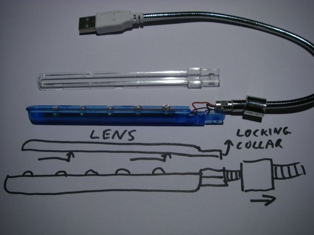
Disassembly will vary from device to device. This one comes apart by pulling the locking ring at the base of the light as shown, then the clear lens slides back to unlock it. If you look closely at the front of the lens you can see the locking slots in it. The point where the flexible neck attaches to the light has a couple of recesses to lock it in place and prevent rotation.
Once you've taken one to bits it should become clear how it goes together.
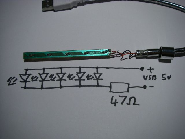
The circuitry varies from light to light. Sometimes there's a resistor per LED and sometimes just one for all the LEDs. This version is the latter. It uses a single 47 ohm resistor which will be dropping 2v, since that's the difference between the 5V USB supply and the LED forward voltage (about 3V). On that basis the current through the circuit will be about 42mA divided through 5 LEDs giving roughly 8.5mA per LED.

This light used what are called "straw hat" LEDs, otherwise known as 4.8mm LEDs. When using them in parallel like this it's a good idea to check the forward voltages are roughly matched. The easiest way to do this is by having an LED gang-bang on a tester as shown above.
With all the LEDs in parallel on one output, any that have a wildly different forward voltage will either be dim or will hog all the current and be the brightest. Weed the odd ones out if required and swap them with others from your pack of LEDs until you find a group that all look roughly the same brightness.

Before removing the old LEDs it's useful to desolder the power connections from the PCB after noting the polarity and marking the PCB if required. It'll make the replacement of the LEDs a lot easier.
When removing the old LEDs I find it helpful to use a bit of silicon aquarium tubing to grip them. It's also useful to flow a bit of fresh solder onto their connections to make it easier to melt with your soldering iron. By pressing the silicon tube on and then pulling gently while you heat both solder joints simultaneously, it's easy to remove the old LEDs.
You may find it useful to note the LED mounting polarity before removing them. Generally speaking the side of the LED with the little anvil shaped chip-holder is the negative side. It may already be marked on the PCB, but there's no harm in marking it yourself to make sure.

You can clean residual solder from the pads using a bit of desoldering wick / desoldering braid or perhaps a desoldering pump. The resin impregnated copper braid sucks the solder into itself when heated with a soldering iron and leaves a very clean pad.

Insert the new LEDs with the correct polarity. The long lead is usually the positive one. I find it useful to kink the end of each LEDs longer lead slightly to stop them dropping out.

Now you can get all ambidextrous like I do, or use an improvised jig (or some tape) to hold the LEDs in place while you solder them. I prefer to solder one lead first (usually the positive one) then check they're all aligned correctly before soldering the other.

Now reattach the power connections with some fresh solder. You could change the resistor value if you want to modify the intensity of your light, but 47 ohms is about right for five parallel LEDs.

Then comes the footery bit where you attempt to reassemble the light again. Be patient and don't force anything. With this light it just required the placing of the PCB and it's lay-on reflector into its position, the tucking in of the excess wire, placement of the flexible neck roughly in position, sliding on of the lens, aligning the gooseneck flats and finally sliding the locking ring into place. Sounds complex, but isn't.
Then plug it into a USB port and see if it works OK.
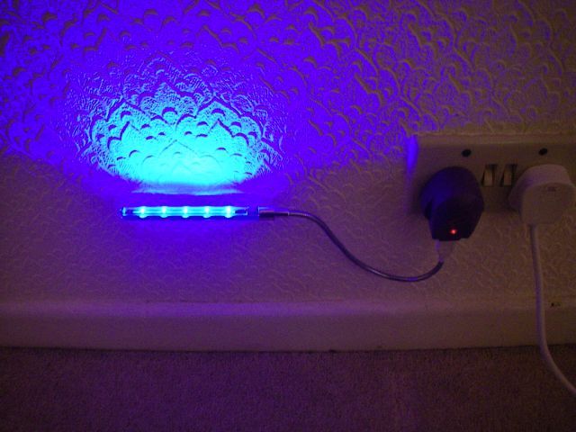
You can also use this as a freestandng light when it's plugged into a USB charger or power supply.