MAKE LED FLOWERS.
Those of you who have browsed this site before may recall the LED bonsai project where I made a ridiculously over the top illuminated Bonsai tree with well over a thousand LEDs. I've now designed a new simpler to build LED flower PCB that is based on a buttercup with five LED petals and an LED stamen. The fact it uses six LEDs means it can be conveniently divided into two three LED circuits with two resistors.
This is an EASY board to assemble. While doing this page I rattled together six LED flowers and had them in a bunch and lit in a remarkably short time.

Here's a cluster of the prototype flowers for this project. It was made with a selection of LED colours and sizes to see which looked best, and to be quite honest they ALL looked good.
You can use a wide range of sizes, colours and types of LEDs in this project, and while my favourites are the 5mm and 10mm diffused LEDs you can also use clear LEDs and the flat-top type. Clear lensed LEDs will give a very dazzling sparkly look to the flowers as you move around them and will also project splashes of colour onto your ceiling and walls. The clear flat-top types will appear as very sharply defined dots of light while the diffused type will give a softer more even illumination.
Be aware that not all LEDs are equal! An older style indicator LED will give out much less light for the same power as one of the newer illumination LEDs. It may be worth getting a selection of LEDs to try them for appearance.
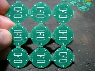
Because of the small size and shape of these boards they are provided in a panelised format and snap out from a frame. Wear hand protection when you snap them out as the edges are quite jaggy!

Although not crucial, I like to file the ridges off where the PCBs snapped apart for a cleaner smoother finish.

First components to get soldered in are two 330 ohm resistors that limit current through the two circuits of LEDs. The resistors can be mounted on the component or track side, but my preference is for them to be mounted on the track side. If you accidentally mount them on the component side then it doesn't matter. A 5mm LED will still squeeze in between them and a bigger LED will sit on top of them.
Technically speaking the resistor should be matched to the combined forward voltage and desired current of the LEDs used, but as a quick general purpose value you can use two 330 ohm resistors. For the more geeky constructors, the resistor that limits current through the circuit that includes the middle LED has a small arrow on the resistor symbol pointing at the middle LED.
I STRONGLY recommend the use of standard lead/tin based solder for hobby soldering. Although its use has been restricted in the electronics manufacturing industry, it is still acceptable for personal or repair use and provides a MUCH better solder connection.

After soldering the two 330 ohm resistors in from the back of the PCB the leads are trimmed flush with the front. Again, if you mounted them on the front instead of the back it doesn't matter. Just leave 'em and it'll be fine.

The leads on the outer "petal" LEDs are now formed by bending them at right angles over the edge of a bit of PCB laminate or whatever you can find that's a similar thickness. It doesn't matter too much what the distance from the LED to the bend is. You could even just bend the leads hard against the LED body if you wish, but I prefer a slight gap.
One important thing to note is that the leads MUST be bent in a manner that means that the longest (anode/positive) lead will go into the hole in the PCB with a plus (+) symbol next to it. Take a look at the picture above and bend the leads in a similar way. I did specifically make all the LED orientations match so that all the petal LEDs can be bent in the same way.

Now the suitably bent LEDs get inserted making doubly sure that the longest lead goes into the hole with the plus (+) symbol next to it. If you discover that this is not the case then you will have to rebend the LED leads in the opposite direction.

Carefully place the LED loaded PCB on your work area as shown and solder all the connections. I prefer to go round soldering just one pin of the LEDs first, then go round a second time soldering the second pin. This reduces the heat build up in the component during soldering.
Soldering just one lead on each LED first also lets you lift the PCB to see if the LEDs have shifted, and will allow adjustment if needed before soldering the rest of the leads.

Now solder in your chosen central "stamen" LED makiing sure the longest lead goes into the hole with the small plus (+) symbol next to it. If you've put the resistors on the front of the PCB then the LED may have to sit on top of them.
This is also a good time to gently bend the petal LEDs so they point forwards a bit to create a more flower-like cup of light.

Next comes the stem, and this should be solid core wire so that it is stiff and supports the flower. You can either twist together two separate solid core wires preferrably with different colours to identify positive and negative, or you can use a piece of commonly available solid core bell wire which has two cores together in a "figure eight" format. There's usually some form of core identification on these cables, either as a band, ridge or core colour.
The wire gets stripped at the end and soldered to the big rectangular pads on the back of the PCB making sure that the positive connection goes to the pad with the big plus (+) symbol next to it. It's useful to flow some solder onto these pads, then tin the wires with a touch of solder before flowing them both together.

And..... Test. The flowers are designed for 12V DC and a regulated 12V supply is preferred.
If the flower lights then it's complete. If it doesn't or part of it lights then there's a good chance that one or more LEDs are inserted the wrong way round or the supply polarity might be wrong. Double check that all the LEDs are in the right way by looking at the little anvil inside the LED which is often the negative terminal. (But not always!) If in doubt compare the LED with any spares you have.

Then make loads more and common their stems together as shown with matching polarity.
Each flower will draw a maximum of 40mA so a 12V 1A supply will easily drive 20 or so flowers.

Voila! A bunch of electric flowers for incorporation into a suitable container or maybe even in a vine format. You could even make a string of Christmas lights by using flexible two core wire. Just make sure that the backs of the PCBs can't short out against each other.