Dodgy halogen chandelier.
This design was inspired by the exquisite halogen and chrome wire chandeliers in the most expensive designer lighting shops. I couldn't justify the high expense of one of those fittings and decided to build my own for fun.
Being an electrician to trade, I've got absolutely no sense of electrical safety at all and decided to make a bare chandelier that operates at 240V with all the lamps in series.
The fitting hangs from a VERY high ceiling, so there is no risk of someone being able to reach up and touch it when it's powered. The fact that it is so completely dodgy just seems to make it more appealing.
This project should not be attempted as it has live exposed metalwork.

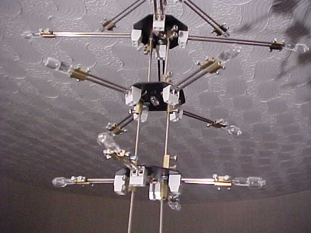
The main part of the assembly is five PCB's like this. They are joined by stainless steel brazing rod inserted into terminals ripped out of terminal strip and clamped to M3 bolts through the PCB. The little neon lamp and resistor is in parallel with the whole PCB's load so that it lights if one of the lamps on that level goes open circuit.

They are assembled into a structure like this using more stainless steel rod to extend the lamp holding arms out from the PCB's.

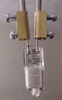
Here's a close-up of the "lamp holder" showing just how simple it is.

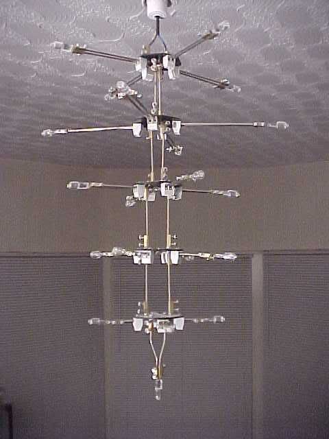
What it looks like assembled and hanging from the ceiling.

Even with 10W lamps, it's just soooo bright! imagine if I fitted 20/50 or even an MCB tripping set of 100W lamps into it instead. With no transformer to worry about it can be fitted with any of those mentioned.
I subsequently added an NTC inrush current limiter in place of the bottom lamp. This has a high resistance when cold which drops as it heats up. The effect of this is to limit the initial surge of current at switch on, and this will ensure a good long lamp life. I also changed to 20W lamps giving a total power of 400W which is quite outstanding when the dimmer's up full.