MAKE A JACOBS LADDER


I remember when I was a very bored kid at secondary school, I discovered a book in the school library called "The Boy Electrician". The book was very old and seemed to assume that it was perfectly acceptable for kids to build their own X-ray machines and mess about with other extremely dangerous apparatus. One of the interesting bits was about a spark coil with a vibrating reed switch that could generate extremely high voltages when powered and could be used to drive such delights as Geissler tubes (early neon tubes), the afore mentioned X-ray unit and various other dangerous devices including a mini Jacob's ladder. At the time it wasn't too practical to build the spark coil due to it's requirement for seemingly outdated and hard to obtain materials (A pound of soft iron wire and a Geissler tube please), but later on when I had left school and started as an apprentice electrician I started to get my hands on all sorts of dubious technical stuff.
It followed that when I salvaged a 10kV 30mA neon transformer from a dead sign, the first thing I did was make a Jacobs ladder by taping some bits of wire to a lovely white formica worktop with masking tape and then applying the high voltage transformer. With a bit of adjustment it soon started to operate and I was rewarded with the gratifying noise and sight of a real live Jacobs ladder. This ended abruptly with a loud pop noise as the HT tracked across the formica worktop leaving a permanent skid mark. This rather offputting finale meant that I tucked the trasnsformer away for future use.
Once you know what a Jacobs ladder is you will easily spot them being used on vintage black and white horror movies, where they were frequently used as part of the apparatus used to bring Frankenstein back to life. F**k knows what they were using for transformers then, but the things were blasting meaty arcs across about 8" (200mm) gaps with ease. Unfortunately it's a bit difficult to get transformers capable of driving the bigger ladders, which tend to use either custom wound transformers or pole mounting power distribution transformers run in reverse with a big choke in series with the secondary. On the other hand, a standard 10 to 15kV neon sign transformer is perfect for making small ladders. The ideal transformer has as high a voltage as you can get. Invariably this is 10kV in the UK and 15kV in the USA, since these are the legal maximum voltages allowed for neon signs. The neon transformers are perfect since they have a current limiting characteristic that stops the transformer from pushing too much current through the arc. The ideal current is basically the highest you can get which in the case of my unit is 50mA at 10kV supplied by an Italian made neon transformer.

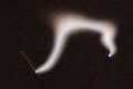
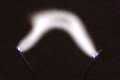
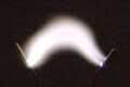
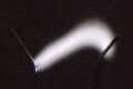
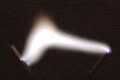
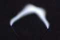
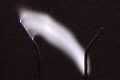
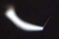
The basic construction and principle of a Jacobs ladder is that a metal vee is formed from two bits of wire and a high voltage is applied across them. The electricity arcs across at the bottom of the vee where the electrodes are closest together. The air that the spark is passing through is ionised making it a preffered route for the arc, so when it heats up and begins to rise it drags the arc up the metal vee pulling it wider as it goes. In a correctly set up ladder the arc will travel all the way to the top where the wires have a sharp outward bend in them to pull the arc apart to the point that it extinguishes and the whole process starts again at the bottom of the vee. Here's a picture of the base of my own Jacobs ladder showing the mounting of the wires.

You will notice that there is a third electrode at the base of the vee, and this is a Gabriel electrode used to make the gap at the bottom of the vee less critical. In a normal Jacobs ladder there is no third electrode and it can sometimes be difficult to balance the shape of the vee for the best results. If the base is too close then the arc won't rise all the way to the top of the ladder because it's easier just to jump the gap at the bottom again. If the base is too far apart then there is the serious risk of the arc not striking at all meaning that the unit will look as if it's switched off when in fact the full voltage is across it. With the limitation of a 10kV transformer I found that the gap was too critical and I designed the Gabriel electrode to solve the problem. It allows the gap to be much wider than normal, but allows the ionisation of the air via two 1 Megohm resistors that make the middle electrode into a semi desireable path for the arc. When the unit is starting an arc it initially jumps over between the middle electrode and the opposing electrode which ionises the air and then pulls the current limited voltage down on the middle electrode. The arc then jumps across the remainder of the gap. It works very well.
This is the transformer I use for my own unit. It is an Italian made F.A.R.T transformer, the initials standing for something like Fabriano Alto Regani Transformatori or something like that. If anything is living proof that a catchy name can sell a product, then the fact that this is the biggest selling neon transformer in the UK must say something. I think I'll call my next product P.O.O.P to see if it sells better. The transformer shown here is a 10kV 50mA unit and the difference between this one and a similar one with only 30mA output is significant.
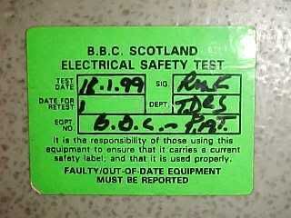
Just one of the many PAT test labels stuck on the transformer from hires to film and TV companies. I think it makes them feel better if they stick a safety label onto something that has two bare wires with ten thousand volts zapping up them. Quite frankly I'm a bit sceptical as to whether this does actually make the unit safer. :)
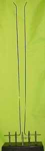
Finally here's the whole unit showing the shape and length of the vee assembly which is 22" (560mm) tall with a half inch (13mm) gap at the base and a 1.5" (40mm) gap at the top just before the arc-breaking flare.
This particular unit has been featured on several TV programmes, films, theatre and music videos amongst various other technical props. If you decide to use a unit like this on set, then you must fit a dead mans switch in series with the power supply. This basically consists of a push button assembly that must be held in continuously to operate the unit. This should be done by an FX technician who has full view of the effect. In the event that something unexpected happens, or an actor gets too close, the power can be cut immediately by releasing the buttons. It is also imperative that everyone in the vicinity of the effect is warned of the dangers associated with contact. While death is very unlikely, a contact would provide an invigorating and memorable experience for the recipient. The unit COULD be encased in a glass or plastic case, but that actually detracts from the whole visual effect of a high voltage device.
Oh yeah, and it's a real show-stopper at parties too. ;)