MAKE AN RGB CONTROL KNOB.
This is a knob based colour changing controller that uses a custom programmed microcontroller to pack a lot of features into a small affordable kit. The module can drive up to 5A (5000mA) per colour at up to 30V to drive surprisingly large arrays of LEDs. This version of the RGB controller uses a knob to scan back and forth through a spectrum of colours for mood lighting. Rotating the knob sweeps smoothly from red to orange to white to yellow to green to cyan to blue to violet and back to red. This makes it perfect for use as a mood light controller.
As a kit it's very easy to build due to the small number of components, clear markings and large chunky pads and tracks. I've deliberately chosen good quality components for this module including professional quality rising clamp terminals, beefy MOSFETs with a low on-state resistance and the chip is supplied in a good quality gold-contact turned pin socket. Fixing hardware for mounting it in your chosen application is also included.
Instructions for using the knob controller are at the bottom of this page.

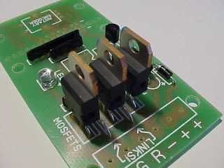
Here's a picture of the complete assembled module ready to go. As you can see it's a fairly straightforward design and you should be able to assemble it quite quickly. Here's a complete step by step assembly guide.
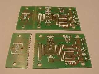
The circuit board is designed to seperate into two parts to let you mount the knob remotely. It's entirely up to you if you want to do that. I've allowed generous pads for the use of a connector or directly soldered wires if you do split the PCB. In most instances I guess the circuit board will be built as a single unit, but it can be carefully cut into the two parts afterwards if desired.
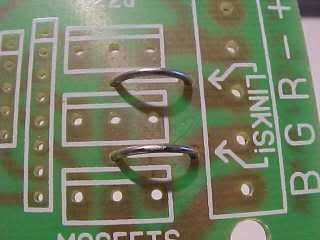
The first things to install are the links. These are important. Without them the red and green channels won't work!
They're simply offcuts of wire soldered in to form a small bridge.
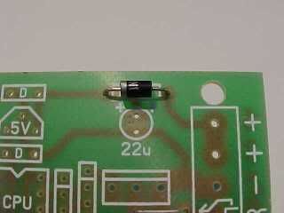
Then we solder in the diode. This is a general purpose 1A type because it's easy to source and is robust and easy to work with. It's a polarity sensitive component and must be installed the right way round. The PCB position is marked 1A and has a line at one side to show which side the little silver band should be mounted.
Now we solder in the resistors, which are actually arrays of resistors in SIL (Single In Line) form. Each of these little black packages contains four resistors. Normally it's important to put these in the correct way round, and there's a dot on the package to mark pin one. However, in this instance I've designed the PCB so you can put them in any way round. Much easier!
The smaller type both contain four 10,000 ohm resistors and are used to pull floating inputs and outputs to a known state. There are integrated pull up resistors in the controller chip, but I chose to add lower value external ones.
The bigger type both contain four independent 1,000 ohm resistors and are used to protect the chips inputs and outputs, and also limit current through the power indicator LED
Take care soldering these components in, as their pads are very close together and it's possible to bridge them with misplaced solder.
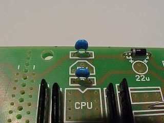
Now we solder in the two little 100nF (0.1uF) capacitors. These are decoupling capacitors and go into the positions marked "D". Their job is to filter any glitches on the processors power supply.
These components are not polarity sensitive and can be soldered in any way round.
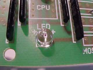
Next is the power indicator LED. This indicates when the circuitry has power and will only work if it's installed the correct way round. The longest lead is the anode and goes to the hole nearest the "+" symbols.
If you chop off the leads and then forget which pin is which, then there is a small flat on the body of the LED next to the negative lead. This corresponds to the flat side of the PCB symbol.
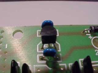
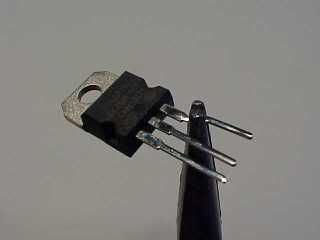
Now we fit the little three pin voltage regulator (78L05) which goes into the position marked 5V as shown.
Its job is to give the controller a nice steady regulated 5V supply.
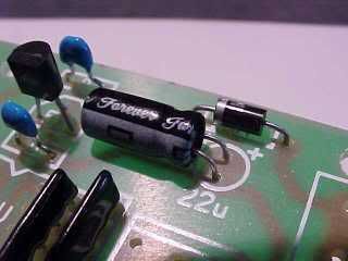
You have a choice in mounting the electrolytic capacitor. You can either leave it standing up on the PCB or lay it down flat. As you can see, I chose the latter. Make sure that the longer lead goes to the side marked with plus symbols. The negative stripe printed on one side should face away from the diode as shown. If you fit that component in the wrong way round it might go POP!
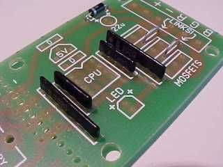
The MOSFETs will need their outer leads bent slightly to make them fit in the PCB holes. This was done to allow much bigger pads and tracks to be used.
Now the three MOSFETs get soldered into position.
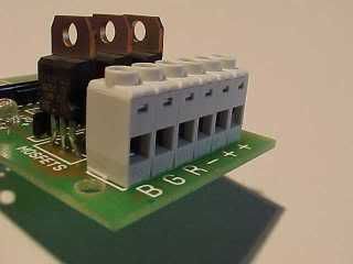
The six way terminal block gets fitted with the wire ports facing away from the MOSFETs. This is an extremely good quality rising clamp terminal block. It's rated for professional use.
If you've every used cheaper versions you'll appreciate it.
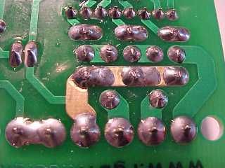
I deliberately designed the PCB with the main current carrying track to the MOSFETs kept clear of solder resist. This means you can flow solder along it to make it beefier if desired.
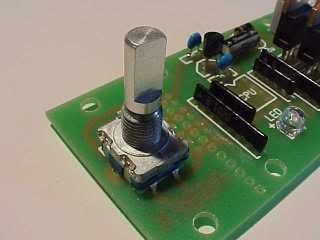
Be extra careful in mounting and soldering the rotary encoder. This is a fairly high resolution gray code unit and has a lot of small contacts inside it. Once you've carefully jiggled the large support pins and the five small connector pins into the PCB, solder the big support pads first, then carefully solder the five other pins without lingering on them with the soldering iron for too long.
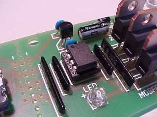
Now the controller chip gets fitted. This is a custom programmed microcontroller that decodes the knobs output and pulse width modulates the RGB outputs. It is supplied pre-fited into a socket. You can either solder it in while still in the socket, or take it out the socket and re-insert it once the socket has been soldered.
Observe the correct positioning. The end of the chip with a notch is marked on the PCB.
Finish the controller by adding the knob to the encoder and the four support feet. There are six holes for the support feet to allow for whether the knob is on board or mounted remotely.
To mount the knob on the shaft it is necessary to pop the lid off the top of the knob (it can be pushed through from the other side) and make sure the internal nut is loosened to allow the collet to slide over the encoder shaft. Don't push it onto the shaft so far that it stops the knob being pressed in, since the encoder contains a push activated switch too. To lock the knob onto the shaft, tighten the nut then replace the lid. The shaft diameter is standard, so you can choose to use other styles of knob too.
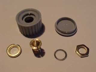
The knob itself has six components! Apart from the grey plastic knob and lid there are four metal components as follows.
From left... The bush has an indent that aligns it in the base of the knob. It's tapered hole should face out. The collet then sits through that bush so that as it's pulled in the taper pushes it's jaws shut to grip the encoder shaft. On the other side of the knob the collet is held in place and tightened with a washer and then nut. The plastic lid then hides the nut.
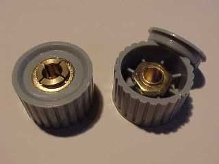
Here's a view of both sides of the knob as assembled.
The controller is connected to your power supply and LEDs as follows:-
"B" The output for the blue LEDs. Pulls down to 0V to illuminate the LEDs.
"G" The output for the green LEDs. Pulls down to 0V to illuminate the LEDs.
"R" The output for the red LEDs. Pulls down to 0V to illuminate the LEDs.
"-" The circuits negative (0V) supply.
"+" The circuits positive supply from 9-24VDC.
"+" Common +ve connection for the LEDs.
This controller is compatible with most common anode RGB LED arrays including the modules on this site.
To use your controller you can turn it on in either of two modes. A brief press of the knob will bring it on in knob control mode where you can turn the knob to cycle through the colours. Turning the controller on with a longer press will bring it on in favourite-colour mode, where it will display a single colour chosen from the full 16 million colour range available.
There are two automatic modes that use a randomiser to select colours then gently fade between them, stopping briefly on each colour. You can enter auto mode from either knob mode or favourite-colour mode by pressing in the knob for about a second. If done from knob mode the auto mode will use a restricted pallete of bright vivid colours, while if entered from favourite-colour mode the auto mode will use the full 16 million colour pallete.
To turn off from any mode except calibration, just press the knob once briefly. The lights will gently fade to black.
The controller software has a calibration facility that is used to balance the output of the red, green and blue channels to achieve very good whites. To enter calibration mode from knob mode you press the knob in continuously for about six seconds until the output strobes red/green/blue. When you release the knob there will be a short red flash to show you are calibrating the red channel. You can then adjust the maximum red intensity by rotating the knob to see how it affects the output (which will display all colours at their highest calibrated output). When you have finished adjusting the red channel, press the knob briefly and there will be a green flash to show you are now calibrating the green channel. On each press of the knob the calibration mode steps round through red, green and blue, so you can keep tweaking each colours output until you get the desired white. To exit calibration mode press the knob in for about a second.
To get the best range of whites in knob mode you should calibrate a cool white. That will allow various shades of white from creamy warm white to icy cold white to be selected from knob mode. You can re-enter calibration mode to tweak the colour as often as you like.
To select your chosen colour for favourite-colour mode, you use the same calibration technique as described above, but by entering it from favourite-colour mode you are actually programming your favourite colour.
When the unit is powered down it remembers the last mode and colour it was in, and when re-powered it will gently fade up into that mode and colour. To ensure a knob selected colour is stored for this feature you have to press the knob briefly to turn the controller off, then again to turn it on again.
If you need to restore all the settings back to scratch, simply power the unit up with the knob pressed in and when it is released it will restore all factory settings.
The short low level glow of a colour at power-up indicates the software version. The first version of the software is the black-release. The second version is the red-release. If you have the earlier version of the software (no start-up glow), then an upgrade chip is available from my web-shop to add the new calibration, whites and favourite-colour modes.