HACK AN LED LAMP.
2023 note - LED lamps have evolved significantly, but can still be hacked to lower power for longer life. See my channel on YouTube (bigclivedotcom) for many lamp hacking videos.
This project is a simple hack to modify an existing generic Chinese mains-powered LED lamp so that it runs its LEDs at much lower power. This will extend the life of the LEDs considerably, including slowing their loss of luminous intensity over time. (LED chips and phosphors degrade in use.) It also makes the lamp ideal for use as a night light or for other applications requiring a low level wash of illumination.
This project is only suitable for the LED lamps that have a large array of small LEDs. It is not suitable for the lamps that use a small group of high power (1 watt plus) LEDs, as those lamps tend to use a current regulated switching supply.
This project involves modifying a mains powered product that was probably built badly in the first place. As such it carries the risk of shock, fire and explosive underpant soiling even when done properly.
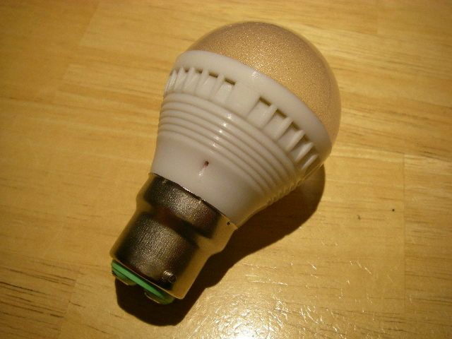
This is a typical LED lamp as sourced from China via ebay. It was rated for 240V and with a completely ficticious power rating of 2.5W.
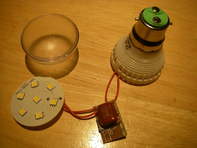
Inside the lamp (which pops open readily with modest pressure) is the LED PCB containing seven 5050 triple LED chips all wired in series to give a total of 21 LEDs with a combined forward voltage of about 65V. The power supply is a very simple capacitive dropper that is extremely common on LED lamps that use an array of ordinary 20mA style LEDs. A capacitive dropper is used as it is simple and extremely efficient. It does not dissipate the voltage drop as heat like a resistive current limiter would, but instead lets a "portion" of current flow through on each half of the mains AC cycle.
This project only applies to the lamps that use a cluster of small LEDs. It is not suitable for the high power LED lamps that use a small number of high power LEDs. (I just thought I'd mention that again.)
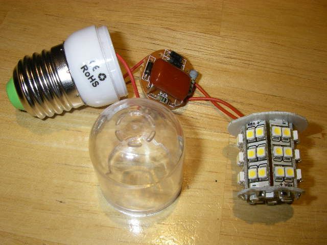
Here's an example of another tubular style of lamp that uses a similar power supply arrangement to limit the current through a series string of 48 LEDs. It's especially exciting to note that some Chinese ebayers are selling similar lamps without plastic domes. Thus exposing anyone putting it into a live lamp holder to a serious electric shock due to the mains derived power supply and open solder connections. AWESOME!

This is the lamps circuit and is very typical of these units with slight variations where the resistor is sometimes placed on the LED side of the rectifier, and sometimes a high voltage low value electrolytic capacitor is used on the DC side to smooth it slightly.
The circuit generally has four components. A capacitor that limits current flow by charging alternately on each half of the mains sinewave, a small resistor rated between 470K ohm and 1 Megohm across the capacitor to discharge it when power is removed, a higher power resistor with a value typically between 220 ohms and 1000 ohms that limits maximum inrush current to protect the LEDs, and a rectifier (sometimes a single module or four separate diodes) that converts the current limited AC supply to DC.
The current flow through the circuit is dependent on the mains supply voltage, the mains frequency, the number of LEDs in series and the value of the capacitor. Typical capacitor values in the United Kingdom on our 230V 50Hz mains are between 100nF and 470nF.

This is the circuit board from the lamp, showing the use of four separate diodes to form a bridge rectifier, the big red metalised polyester capacitor used to limit current, it's small 1 megohm discharge resistor and a 680 ohm metal film resistor rated at about a watt that will also probably double up as a crude fuse if the circuit fails.
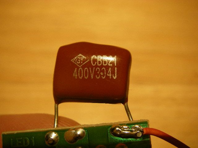
This is the bit we want to change. At the moment it's a 330 nano Farad capacitor rated at 400V to allow for the peak voltage of our UK 230V supply. I'm going to change it for a 100nF capacitor that will effectively pass less than a third of the current.
If you want the maths to get a rough guide to the current in the circuit then read on. If not, then skip to the next step.
To get the current through the circuit we need to subtract the total forward voltage of all the LEDs from the mains voltage. So for the light being used here it would be a 230V supply minus the 63V across it's LEDs (number of LEDs times 3V), giving a total voltage to drop of 167V. Now we have to calculate the effective resistance of the capacitor called capacitive reactance. The formula for this is 1 divided by (2 Pi F C) where Pi is 3.14, F is the mains frequency (usually 50 or 60Hz) and C is the capacitance in Farads. Keep in mind that the capacitors we are using are in nano Farads!
I'll save you the mathematical grief by saying that 100nF has a rough reactance of 32K ohms, 220nF = 16K ohms, 330nF = 10K ohms and 470nF = 6K ohms. These are very rough values for reference. There's a whole load more maths that can be applied, but we'll leave that to the geeky savants.
Based on that, the original current through the LEDs would have been around 16mA, but will reduce to around 5mA after the cap has been changed for a 100nF one.
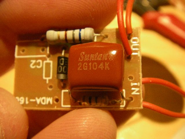
Job done! Quite easy to do, particularly with a bit of desoldering wick to help suck up the excess solder. The new capacitor is a 100nF 400V metalised polyester type The code on it is as follows:- 2G104K which breaks down as 2G=400VDC 104 is one, zero and four zeros in pico Farads 100000pF = 100nF, and the K means 10% tolerance. Can I be honest? I had to research the 2G=400V bit. Most of these caps just print the voltage on the case, but this one being small they'd used an industry standard code for the voltage. The digit 2 made me wonder if my supplier had sent me an under-rated 200V capacitor, but after a LOT of Googling I found that the 2G does actually indicate 400V.
Now reassemble the lamp taking care to ensure that the power supply board and LED board are adequatley separated to avoid short circuits.
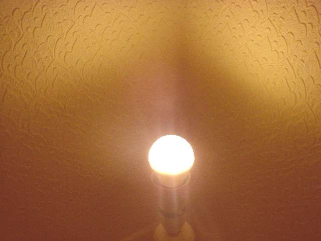
Plug it into an unenergised lamp holder and get someone else to switch it on while you stand at the other side of the room, close your eyes tightly, clench your teeth and put your fingers in your ears. No bang? Oodles of LED loveliness? Job done!