MAKE A CHEAPO NEON PSU
(A simple but incredibly reliable way to get a touch of neon around your workshop.)
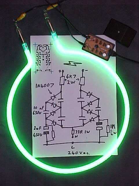
This picture just about says it all...
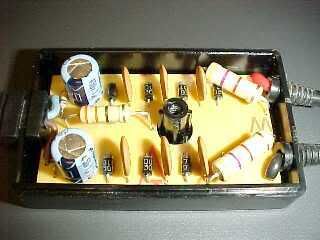
But here's a close up of the PSU anyway.
Click here for the track and layout of this PCB in TIF format
HOW IT WORKS
The simplicity of this design is astounding. I've had several of these circuits running continuously (24/7) for about ten years and they're still going strong. It's not perfect though, since there are invariably a few compromises due to it's minimalist design. The most important is probably the fact that it drives the tube with DC which means that the mercury in the tube tends to migrate towards the cathode and after a long period of use the anode end of the tube will start to darken as the mercury completes it's journey to the other end of the tube. This is easily remedied by either reversing the tube connections, or just shaking the bead of mercury back over to the anode. The polarising effect can be put to good use in a tube charged with neon and mercury, since if a mercury trap is built into the middle of the tube, then the tube can be two colours at once! Red at the anode side, then suddenly fading to blue at the cathode side. (It will take a long time for all residual mercury to migrate from the tubes anode before this effect occurs.)
Perhaps I should point out that the design cannot drive neon tubes that are actually charged solely with neon. It tries, but just can't maintain a current through them. However, it performs admirably with argon/mercury tubes, which means that it can be used to illuminate a wide variety of phosphor colours.
PRINCIPLE OF OPERATION
The unit is designed to work directly from 240V AC mains power. It basically consists of two diode/capacitor voltage multipliers and a couple of current limiting resistors. The first stage of both multipliers is a 1uF 450V capacitor, and this acts as a smoothed DC supply to run the tube once it has struck.
neon/argon/mercury tubes require a high voltage to get them started and the higher strike voltage is provided by the later stages of the voltage multiplier. Because these are only there to strike the tube and not run it, they can be low value capacitors (10n 1kV) which makes them more compact. The output resistors are to limit the current through the tube since otherwise it would try to sink as much current as possible. The low value of the supply capacitors means that the voltage across the tube tends to sit down across the tube and resistors, and this means that the resistors don't get too hot in operation.
Generally speaking the picture above tells the whole story. It shows the circuit schematic lit by the actual circuit and a suitable tube.
DRIVING CAPABILITY
The circuit is best suited to argon/mercury tubes of about 24" (600mm) in length. It can drive more, but tends to make the longer tubes shimmer a bit and sometimes can't strike them reliably. Very short tubes will cause the output resistors to heat up significantly and may even roast them, but it's easy to change them to get the circuit running again.
Initially a new tube may shimmer and stay dim or repeatedly strike and extinguish until it has adjusted to being run on a DC supply, but after it has been lit for a while it will happily light up instantly in future. The circuit drives the tube at around 15mA with only the cathode heating up. It uses about 4 watts of power which is peanuts given how bright the tube looks, and this also means that it can be left on continually without guilt. Because of the low mains current requirement the circuit can be switched with nothing more than a triac opto isolator if a touch of animation is required.
This is a nice rugged little circuit that is well suited to technically minded users. It's cheap, simple and best of all it's servicable.