STOP YOUR XMAS LIGHTS FLASHING!
Note that this page is only for the older style strings of lights. The new ones with alternating polarity on two wires are much harder to hack to a static mode.
I'm not sure why the Chinese manufacturers think we like flashing Christmas lights, especially ones fitted with those awful little mass produced flashers that invariably reset to the demo mode every time you turn the lights off. Then when you press the button until you get to what you thought was just static lights, it suddenly starts to fade them up and down!
So here's how you can disable those pesky controllers for good. Or better still, replace them with a tiny little rectifier.
This project can involve working with mains voltage of enough amplitude to blow the Christmas spirit right out of you and potentially turn you into the ghost of Xmas misfortune. There's also the (amusing) possibility that you might set fire to your Xmas tree if you modify your lights incorrectly. It's also noteworthy that some cheapskate companies supply lights with controllers that have no static mode because the transformer can't handle the full load of all the lights being on at once, but these are rare.
Best of all, some really nasty lights from China commonly sold on ebay are so inadequately built that you can get smoke off them just by setting the static mode on the supplied controller. AWESOME!
No liability will be taken for death, fire, destruction of giftwrap or loss of Christmas spirit. You tackle this project entirely at your own risk.
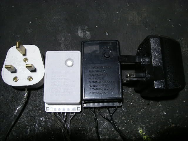
Here are the culprits. Mass produced flashers used either on mains voltage or with 24V transformers. Note the white one with the UK square pin plug is running on 240V and has totally inadequate wiring. It was one of many dodgy delights bought directly from China on ebay.

The controllers can be either clipped or glued together. If they are glued then they will be hard to get apart. If they are clipped then they will pop right open with very little effort, just like the 240V one did! In fact a child could have opened it, exposing live mains connections!

The circuitry in these things is very standard. There's a rectifier consisting of four diodes, a small PCB that slots into the main PCB that has the control chip on it under a blob of resin, a few support components and between one and four small thyristors for switching the lights. Thyristors are usually used because they are easy to drive and are well suited to the phase control used for dimming effects. The number of thyristors used will depend on the number of flashing channels and how cheap and nasty the Chinese manufacturer was. Some use all four, some use two, the very odd ones use three and the nastiest use just one.
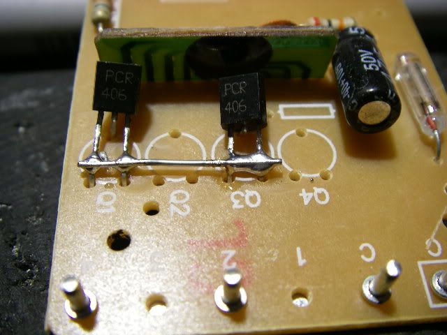
The easiest way to stop the flashing is just to short out the thyristors. They have three pins, and the ones that are closest to the control chip are usually the control pins, while the other two are usually the switching side (anode) and the common negative (cathode). It's easy to just bridge across the anode and cathode with a bit of wire, and since they all share the common negative you can just bridge them all with one bit.
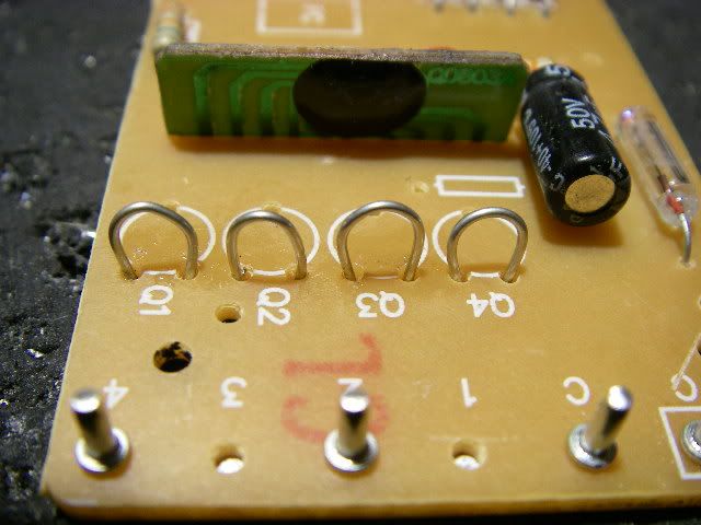
A neater way is to replace the thyristors with wire links.
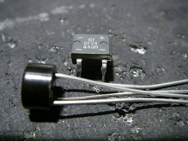
My preferred approach to stopping the flashing is just to replace the controller with a bridge rectifier. This effectively removes all the control circuitry and just feeds the lights unswitched DC. You will have to choose a rectifier based on your lighting string. For a 24V string you can use a common 1 Amp 50V rectifier, but for higher voltages you will need to use a rectifier with a suitable voltage rating. On 240V I used a 400V rectifier, but on 120V a 200V unit should be ideal. Most home lighting strings will be fine with a 1 Amp rectifier, but larger "industrial" strings may require a higher current rating.
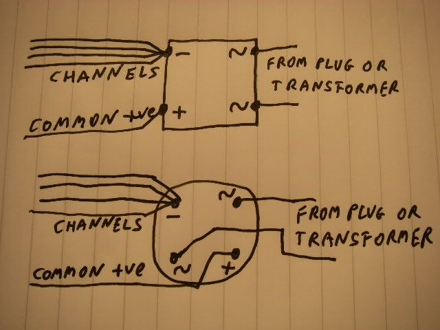
Bridge rectifiers have four pins. The two with a squiggle next to them are the AC pins and will be connected to the mains supply or transformer output. Polarity is not important since it is AC (alternating current). The other two pins on the rectifier are the positive (+) and the negative (-) outputs. The lighting string will generally have one common positive connection, and between one and four negative connections for each channel of lights.
The common connection will go to the positive (+) pin of the rectifier and the other wires will be commoned together and connected to the negative (-) pin of the rectifier.

If the connections on the controller are not marked as shown on the righthand controller above, then you'll need to work out the connections by tracing the tracks on the PCB. The power-in connections from the plug or transformer will usually be next to each other and will usually head straight to the four diode rectifier on the PCB. The output channels should be obvious because the tracks will go straight to the little thyristors. The common positive for the lights will often be at the opposite side from the two power connections, but not always. If you can work out what the power connections (from the plug or transformer) are and then deduce the outputs then the only remaining connection should be the common positive for the lights.
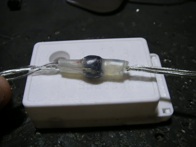
For a mains set I used a small DIL style rectifier rated for 0.9 Amp at 400V. I soldered the mains connections to the AC pins and the lights to the DC (+/-) pins. I then tacked the wires in place with hot melt glue, used a bit of heatshrink sleeving to cover the rectifier and filled the remaining cavities with more hot melt glue to act as a simple cable grip and make the assembly more robust to avoid damage.
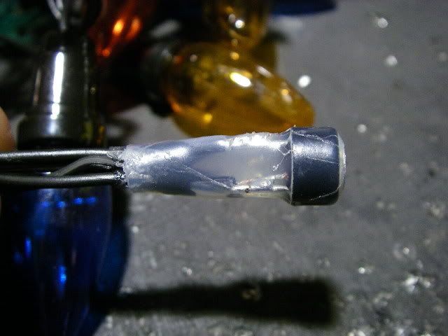
For a low voltage set (24V) I used a common 1 Amp 50V rectifier and again connected the output from the transformer to the AC pins and the lights to the DC pins, applied the heatshrink and filled the assembly with hot melt glue.
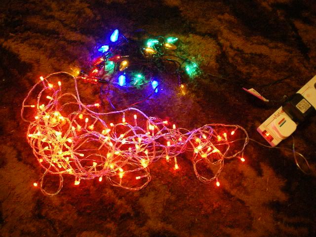
And there we have it. Two sets of lights that don't flash any more, and also don't have that horrible little controller.
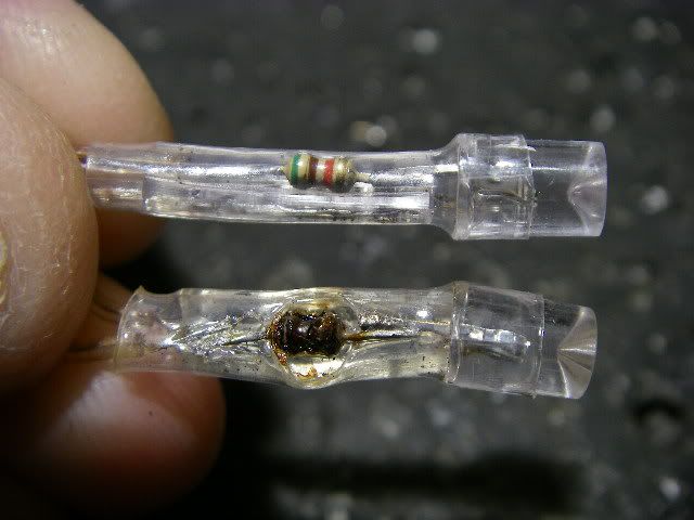
Spectacular. This is a cheap set of Chinese LED lights bought on ebay. Aside from the fact that the tiny inline resistors are a mix of values, they are grossly under-rated for the job they are doing, even if the controller is flashing them on and off. I'd say the resistors are rated at 0.125 Watts, and in the string that has already smoked there were three 3000 Ohm resistors in series with about 33 red LEDs. Given that a typical red LED has a forward voltage of about 2V that would give a total LED voltage of about 66V leaving 174V to be dropped across the resistors on a 240V supply. The total resistance of all three 3000 Ohm resistors is 9000 Ohms, so the average current will be roughly 19.33mA (which is good) but the dissipation across the resistors will be 3.36 Watts meaning that even with the current split over three resistors they are dissipating ten times their rated value! No wonder they went up in smoke.
This happened while the original controller was still in use and set at static. I was playing with the LED string while it was on (highly dubious thing to do given the quality) when I noticed a hot smell and then felt a burning sensation from one of the resistors. For all it would have taken to add a few more resistors in series along the string, I really don't know why China puts stuff like this out.
I also spotted defective wire in the string which actually had wire strands emerging from the plastic insulation. That's definitely a serious shock risk. Definitely one for the Chinese deathtrap collection.