MAKE A POWER SAVING PLUG.
Just plug one of these amazing devices into any socket in your house and save up to 35% on your electricity bill. It sounds too good to be true. Lets take one to bits so we can copy it and save lots of money.
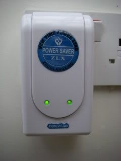
Here we go. I've plugged the miracle plug in and it's now saving me lots of money. I can tell it's saving me money because two green LEDs on the front have lit up.
OOH! I'm so excited. I must open it to see how it saves me so much money!!!
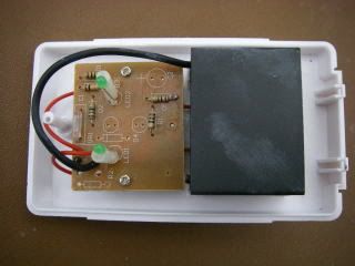
Oh dear! It appears to contain a big capacitor like the ones found in cheapo strobes and it appears that one of it's wires has been cut off so it's not doing anything anyway.
If the capacitor had been connected then the unit would have had a limited effect of compensating for the power factor of inductive loads in the house, but this would be hit or miss and would not affect the power meter significantly anyway.
There is a position on the PCB for a MOV (Metal Oxide Varistor) which is normally used to clamp high voltage transients. Since these components tend to fail HOT they should be used with a thermal fuse in series, and since there's no place for one on this PCB it's probably just as well there's no MOV in use.
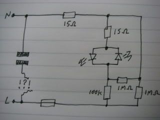
Here's the nonsensical schematic which shows 15-ohm resistors being used as links, a 1 Megohm resistor that could have slowly discharged the capacitor had it actually been connected, another 1 Megohm resistor doing virtually nothing, two ordinary 3mm LEDs in inverse parallel so they light on alternate polarities of the mains waveform, a 100K resistor to limit the current through the LEDs and a fuse in case something goes short circuit (it wouldn't have protected the MOV or capacitor!).
I'm not sure about the logic behind using 15 ohm resistors as links. Their colour code is so close to the 1 Megohm resistors (brown, green black versus brown black green!) that they could get mixed up easily during manufacture, and putting a 15 ohm resistor across the mains would be very exciting (briefly).
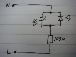
And here's the equivalent circuit of the plug once all the superfluous tat is removed. A quarter watt 100K resistor with two LEDs in inverse parallel across the mains. Although the resistor is rated at 0.25W it's actually being used at nearer 0.6W on the UK's 240V supply, so it gets a bit hot and smells all resistory when the plug has been "saving power" for a while.
OK, so that's how you make a power saving plug. All you need is a plug-box, a couple of LEDs and a 1 watt 100K resistor. If you're in America use a 47K resistor or the LEDs are going to be even dimmer.
UPDATE.
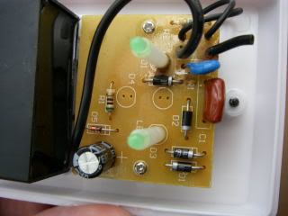
Here's another identical plug with a slightly different label. This one also has the capacitor disconnected, but does have a (non thermally protected) MOV. The mystery of the weird circuitry for lighting a couple of LEDs is also revealed in the schematic below.
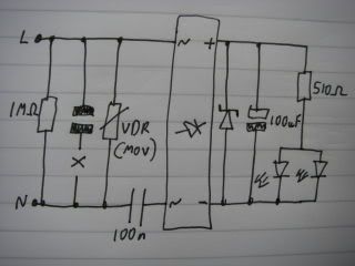
This must be the "luxury" model with almost all it's components in use. The most notable feature of this plug is that the LEDs are powered from a fairly sensible (but not perfect) power supply. It uses a 100nF capacitor in series with a bridge rectifier to limit and rectify the current to provide a smoothed power supply for the LEDs courtesy of the 100uF capacitor and it's parallel zener. There is a 510 ohm resistor limiting the current through two parallel LEDs. Ironically, if they had put the LEDs in series they would have been brighter and more evenly matched. They could also have ditched the Electrolytic and zener if they'd wanted to make things simpler.
It still doesn't reduce your power bill though.