MAKE LED FLOODLIGHTS.
A new version of this design made with superflux LEDs and manufactured PCBs is featured as another project on this site!
Now this is a good beefy project. It's a PCB that retrofits into a generously sized 500W halogen style floodlight casing. It replaces the existing lamp with a panel of 180 LEDs that can project a wide variety of colours using RGB colour mixing. The PCB is fully compatible with the RGB controller in the previous RGB project, and several of these lights could be driven in tandem to provide a strong colour wash.
The use of an existing floodlight case means that the units are rugged and waterproof. The PCB can also be fitted into a standard industrial plastic enclosure with a clear lid.
It may be worth looking around for the 500W halogen fitting with the bulkiest case, since due to the ever reliable Murphy's law I designed the PCB to fit the first case to hand which it appears was quite a big one. Some of the cheaper lights have such skimpy cases that the PCB may not fit or you may have to get busy with a Dremmel to remove excess protrusions.
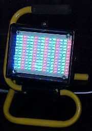
Here's a picture of a complete RGB floodlight in a site style stand.
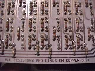
The LEDs are all mounted on the front of the PCB, but the resistors and links are mounted on the back. (Just like it says.)
I've used resistor style links in this application. They are the devices that look like resistors, but have a single black band on them.
The choice of resistors will depend on the type of LEDs, the number in each circuit and the residual voltage to drop across the resistor. In this design the red LEDs are wired in series circuits of four to give a total forward voltage of roughly 8V. A resistor of 180 ohms should be used for these on a 12V supply. The greens and blues are wired in pairs and will have a voltage of between 6 and 7 volts. A resistor value of about 270 ohms should be used on a 12V supply.
The resistors and links should be fitted first, then their leads cropped on the component side before fitting the LEDs. A PCB assembly jig that holds the components in place with foam is very helpful for this project.
All LEDs should have their anodes (long lead) in the direction of the side of the PCB with a row of "+" symbols. The circuits are all common anode with the cathode for each being pulled low to turn on the LEDs.
The track layout has been specifically designed for thermal management and the resistors are connected to the anodes of the LEDs to minimise their impact on the temperature of the chips that are generally mounted on the cathode terminals. A short length of track has been included between the resistors and LEDs to help with heat dissipation.
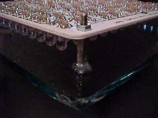
To make the PCB as universal as possible, it actually fixes onto the front glass of the floodlight instead of attempting to use internal fixings. It achieves it's mounting using standard brass spacers mounted at each corner of the PCB.
The glass front of most of these cheap halogen floodlights can usually be removed. If it can, then take it out and with the spacers pre-mounted to the PCB apply some two part resin or silicon to the brass spacers and carefully align the PCB centrally on the glass.
This mounting arrangement ensures that the LEDs are held in perfect alignment with the glass regardless of the floodlight type. It also allows the PCB to be easily removed from the glass if required.
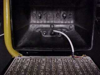
Remove the existing reflector, lamp holder and wiring from the inside of the floodlight case and feed the PCB cable through the back ensuring that the cable doesn't lay across the resistors when the lid is hinged shut.
The cable can either be taken directly through and out the units sealing gland, or it can be terminated in a four way terminal block in the connection area.
If the unit is going to be used indoors, then it will be useful to drill some ventillation holes in the case as the large array of LEDs and resistors will get warm when used at high intensity levels.
The choice of LEDs is up to you. I strongly recommend the cheap trash Chinese LEDs for this application for cost reasons, and you should expect a few to go out here and there depending on the manufacturing quality. These can easily be replaced and after a burn in period the defective LEDs should all be weeded out.
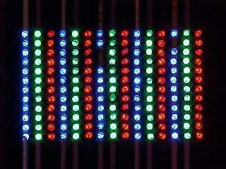
The red LEDs tend to be completely reliable, but the newer technology greens and blues are extremely temperamental. There are two common failure modes of these LEDs. The least likely is to fail open circuit. This is no big deal, the LED and any others in series with it go out. The most likely failure mode is short circuit and this will happen progressively often starting with random flickering. When the LED goes short circuit the forward voltage of that group of series LEDs drops by the value of an LED and the circuit will pass a much higher current. This will sometimes nuke the other LED and maybe the resistor too if the current is high enough.
No big deal, this design is for personal use and it won't take long to stick in a couple more LEDs.
In the picture above, there is an example of a shorted LED (the single one out at the right hand side), an open circuit LED (the pair in that circuit have gone out), and an LED that isn't sitting flush with the PCB. It looks dim because it's firing it's light in a slightly different direction.
For better colour mixing and a wider beam angle you can use some light diffusion material over the front of the PCB or fitting.
To download the image files for this project you should right-click the following links and save the target file to your desktop. This can then be opened in PAINT or another suitable program that handles TIF files correctly. The advantage of using a TIF file is that the image should be printed out at the correct scale.
Click here for the track layout of this PCB in TIF format
This file is a high resolution TIF file that should allow you to laser print a transparency directly. The toner side of the transparency should be placed in contact with the copper PCB when exposing.
Click here for the component layout of this PCB in TIF format
This layout image is for reference only. It gives a rough alignment of the components, but most information is available on the back of the PCB itself.