MAKE A MINIATURE RGB CONTROLLER.
A new smaller, simpler and cheaper version of the very popular RGB controller that is ideal for building into your applications. It has its own version of the RGB software that lets it do lots of tricks, but slims the number of programs down to make it easier to navigate through the effects. It's still got the 8 million bit randomiser and 16 million colour pallete of the original controller.
Ideal for all the DIY LED panels I feature on this site and most other common anode RGB LED arrays.
This version of the controller is designed to run from a DC supply voltage of between 12 to 15V.
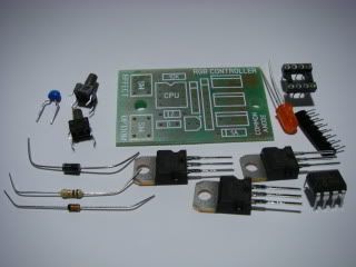
All the components required for this very simple to build kit.
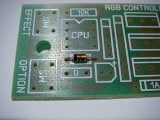
It's usually a good idea to start with the smallest components and work upwards in size. In this case we start with the zener diode. If you look at the PCB you will see a component marked "Z". The black band on one end of the diode MUST match the band shown on the PCBs component marking.
The function of this component is to provide a stable regulated 5V supply for the controller chip.
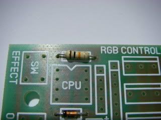
The next component to go in is the 10,000 ohm resistor. The function of this component is to ensure that when the circuit is powered down the supply to the chip is dragged down to near zero quickly to ensure a proper reset. The resistor can go in any way round, and goes in the positon marked 10K. The colour bands indicate the resistors value and read Brown (1) Black (0) and Orange (3) which gives the value as 10 and three zeros = 10000 ohms.
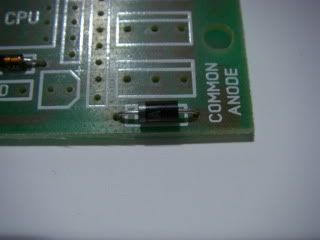
Now we install the polarity protection diode. This is a general purpose 1A rectifier diode and goes in the position marked 1A. Polarity of this component is important, so the band on one end must match the band on the PCB.
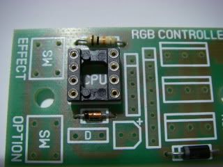
Next is the socket for the chip. It may vary in appearance from the one shown in the picture above, but will have the same function. There is an indent in one end of the socket which must match the indent shown on the PCB. This it to help ensure that the chip gets plugged in the right way round.
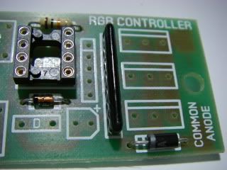
Next is a SIL (Single In Line) resistor array. This component has eight pins and has four serparate 1000 ohm resistors in it. There is a polarity dot on one end, but in this application the resistor array can go in either way round. It will be obvious where it goes in the PCB. This component has four resistors, three of which are in series with the MOSFET gates and one which is part of the power supply.
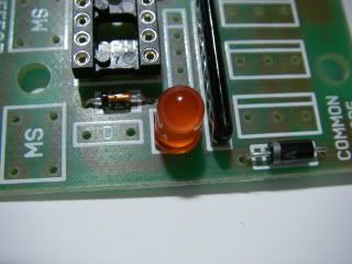
Another polarity sensitive component, the power indicator LED. The long lead goes to the end of the PCB marking with a small "+" symbol.
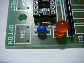
The decoupling capacitor goes in the space marked "D" and it is used to reduce the risk of glitches on the power supply interfering with the control chips operation.
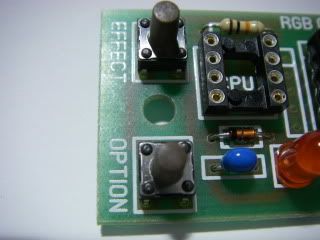
Now the control buttons go in. They should only fit in one way round and will push into the holes with a slight friction fit to help keep them in place as they are being soldered.
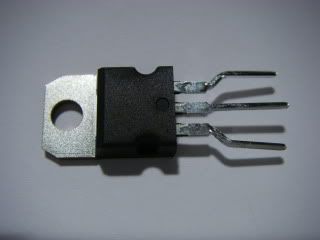
The MOSFET transistors are the main load switching device and will need their legs bent into shape before insertion into the PCB. This adjustment is best done with a pair of thin long-nose pliers.
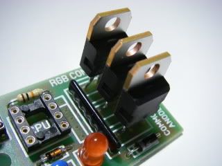
The MOSFETs go into the PCB as shown, making sure they are the right way round.
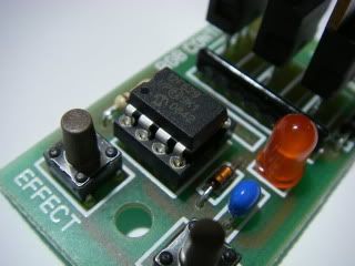
Now the chip is carefully inserted into it's socket, making sure that the pins don't bend as it gets pushed in. This chip is a PIC12F629 microcontroller preprogrammed to near full capacity with my own software.
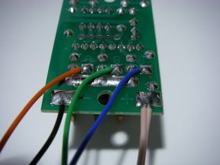
To keep size and cost down, this module uses direct soldered wire connections as shown.
"B" The output for the blue LEDs. Pulls down to 0V to illuminate the LEDs.
"G" The output for the green LEDs. Pulls down to 0V to illuminate the LEDs.
"R" The output for the red LEDs. Pulls down to 0V to illuminate the LEDs.
"-" The circuits negative (0V) supply (black wire).
"+" The circuits positive 12V supply (pink wire to avoid confusion with the red channel).
"+" Common +ve connection for the LEDs (pink again).
When soldering on your leads it's a good idea to flow some solder onto the pads and also tin the ends of your wires with a touch of solder, then place each wire onto its pad and reflow the solder to join the two.
If you'd rather connect your lights using screw terminals, then there is a larger version of this kit that has terminals, mounting hardware and more program features.
Click here to view a printable list of the effects.